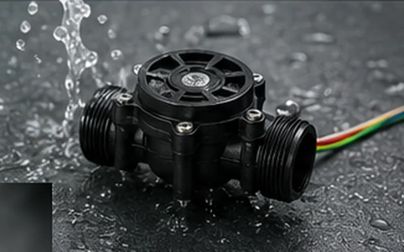
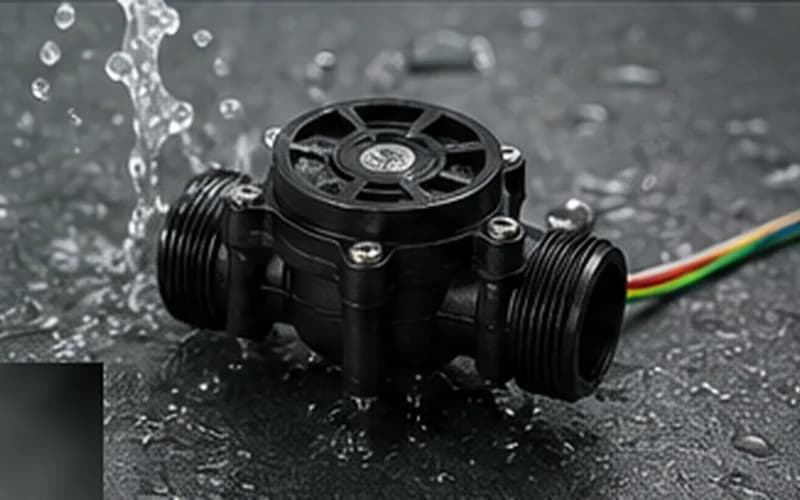
The flow sensor is the trigger that starts every hot water heating cycle. It is a small turbine or Hall-effect device on the cold-water inlet that converts water velocity into a digital pulse signal. The control board reads this pulse frequency to determine: (1) is water flowing? (2) at what rate? Both pieces of information are used to activate the burner and modulate gas output. When the flow sensor fails or gives inaccurate readings, the symptoms can look exactly like a gas, ignition, or temperature problem — which is why flow sensor diagnosis is so frequently overlooked.
How a Tankless Flow Sensor Works
Most tankless flow sensors use a Hall-effect mechanism: a small turbine wheel spins in the water stream as water flows past. A magnet embedded in one of the turbine vanes passes a Hall-effect sensor on each rotation, generating a digital pulse. The control board counts pulses per second — more pulses = more flow. The board converts this into a GPM reading and compares it to the activation threshold.
| Pulse output (typical) | Approximately 5.5 pulses per liter (varies by brand — 4.8–6.5 pulses/liter range) |
| Signal type | 5V DC digital pulse (square wave), one pulse per turbine revolution |
| Activation threshold (Navien NPE) | 0.50 GPM / 1.89 LPM |
| Activation threshold (Rinnai RL/RU) | 0.40 GPM / 1.51 LPM |
| Activation threshold (Rheem RTG/RTGH) | 0.50 GPM / 1.89 LPM |
| Activation threshold (A.O. Smith ATI) | 0.40 GPM / 1.51 LPM |
Symptoms That Point to Flow Sensor Failure
Flow sensor faults present in several ways depending on the failure mode:
- checkUnit does not fire with adequate flow and shows a low-flow or no-flow error code — turbine is seized or magnet has failed; sensor is not generating pulses.
- checkUnit fires at very low demand (barely open faucet) but not at normal demand — turbine is partially seized, producing pulses only at very low RPM where the vane drags slowly past the sensor.
- checkErratic temperature output with no other apparent cause — turbine is spinning but at inconsistent speed due to partial blockage; PCB modulates gas incorrectly based on inaccurate flow reading.
- checkUnit fires intermittently — wiring to the sensor has a loose connection that breaks under vibration, causing the flow signal to drop out mid-cycle.
- checkFlow error code on a unit with confirmed adequate water flow — sensor is not generating output even though the turbine spins (Hall-effect element has failed).
Testing the Flow Sensor — Step-by-Step
This test procedure works on all brands. You need a digital multimeter.
- checkStep 1: With unit powered on and a hot water tap open, locate the flow sensor wiring connector at the PCB. The connector typically has three wires: VCC (5V supply), GND (ground), and SIGNAL (pulse output).
- checkStep 2: With the multimeter set to DC voltage, measure across the VCC and GND wires at the connector. Should read 4.5–5.5V DC. If not, the PCB supply rail is faulty.
- checkStep 3: Move the probes to measure between SIGNAL and GND while water is flowing. A functional sensor produces a rapidly pulsing voltage between 0V and 5V. The pulsing is fast — at 1 GPM, it pulses approximately 90 times per minute.
- checkStep 4: If SIGNAL reads a constant 5V or constant 0V with no pulsing while water is flowing, the turbine is not spinning or the Hall-effect element has failed.
- checkStep 5: If SIGNAL pulses correctly but the unit still shows a low-flow fault, compare the pulse frequency to the expected rate for the measured flow rate. An abnormal pulse rate indicates a turbine with a broken or missing magnet vane.
Set your multimeter to AC voltage if the DC pulsing is too fast for the display to capture. AC mode shows the RMS value of the pulse signal — a functional sensor reads 2–3V AC at normal flow rates. Zero AC voltage = no pulses = sensor failure.
Cleaning the Flow Sensor
Before replacing the sensor, attempt cleaning — especially in hard-water areas where mineral scale can coat the turbine vane and reduce its rotational speed.
- checkClose the cold-water inlet valve. Release pressure by opening a hot faucet.
- checkRemove the sensor from its housing (usually a 1" BSP or NPT fitting with a snap-ring or clip retainer). Some models use a hex union.
- checkInspect the turbine wheel: it should spin freely with a gentle finger touch. If it is stiff or seized, scale is the cause.
- checkSubmerge the turbine assembly in white vinegar (5% acetic acid) for 20 minutes. Agitate gently. Rinse under running water.
- checkSpin the turbine by hand — it should rotate freely with almost no resistance.
- checkCheck the turbine vanes for chips or cracks. A damaged vane changes the pulse frequency. If vanes are broken, replace the sensor.
| Turbine free-spin resistance | Should spin with < 5g of finger pressure. If stiffer, scale is still present. |
| Hall-effect element visual check | Look for corrosion on the PCB-side contact pins of the sensor connector |
Replacing the Flow Sensor — What to Know Before Ordering
Flow sensors are brand-specific and often model-specific within a brand. Using an incorrect-specification sensor causes inaccurate flow readings.
- checkMeasure the flow sensor's fitting thread size before ordering: 3/4" NPT, 1/2" NPT, or 1" BSP are common.
- checkConfirm the pulse-per-liter specification of the OEM sensor — an aftermarket replacement with a different pulse rate will cause the PCB to modulate incorrectly. Some PCBs allow pulse-rate calibration in the service menu; others do not.
- checkAfter replacement, run the unit through five complete heating cycles and verify output temperature is stable — confirming the PCB is correctly interpreting the new sensor's output.
Do not install a generic irrigation or HVAC flow sensor as a replacement — these use different pulse rates and different voltage levels. Only use OEM or OEM-equivalent parts.
Video Guide
Tankless Water Heater Flow Sensor Not Working — How To Fix It
Use HeatDiagnose for guided step-by-step repair
Enter your brand, model, and error code — and get a yes/no diagnostic flow built from OEM service procedures.
Frequently Asked Questions
Can a clogged inlet filter screen mimic a flow sensor fault?expand_more
Yes — and this is the most common diagnostic pitfall with flow sensor codes. A partially blocked filter screen restricts flow below the activation threshold. The sensor correctly reports low flow. Clean the screen before testing or replacing the sensor.
How long do tankless flow sensors last?expand_more
In clean, sediment-free water: 8–12 years. In hard water or sediment-heavy supply water: 3–5 years. Annual flushing of the inlet filter screen and periodic descaling extends sensor turbine life significantly.
What causes a flow sensor to stick at low flow but work at high flow?expand_more
Partial scale on the turbine vane increases its rotational drag. At very low flow rates, the water velocity cannot overcome the drag and the vane stalls — no pulses, no ignition. At higher flow rates, the water force is sufficient to push the vane past the resistance. The fix is chemical descaling of the turbine, as described above.