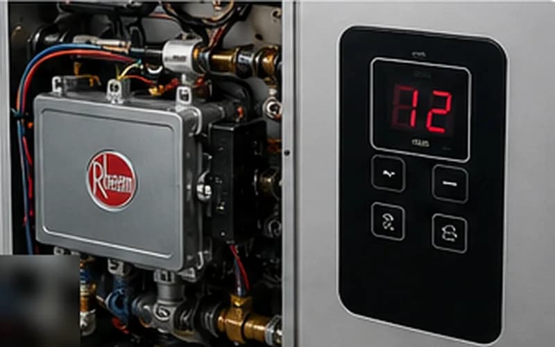
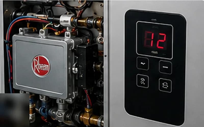
Rheem tankless water heaters display numeric fault codes on the front LED panel. Each code identifies a specific subsystem fault — but the code alone does not identify the failed component. This guide covers every code encountered in the field on RTG and RTGH series units, with the complete diagnostic procedure for each. Work through the full sequence for each code before ordering parts.
Rheem Error Code 11 — Ignition Failure
Code 11 is the most frequently reported Rheem fault. The unit attempted ignition and the flame sensor did not confirm a stable flame within the allotted window. The full diagnostic procedure is covered in our dedicated Rheem Code 11 guide, but the core sequence is:
- check1. Verify gas shutoff valve is fully open and dynamic gas pressure is ≥ 3.5" WC (NG) or ≥ 8.0" WC (LP) under firing conditions.
- check2. Clean the flame sensor rod with 0000 steel wool. This alone resolves ~45% of code 11 cases.
- check3. Inspect air intake and exhaust terminations for blockage, ice, or debris.
- check4. Clean the cold-water inlet filter screen and verify flow rate ≥ 0.5 GPM.
- check5. Test igniter electrode resistance (target: 10–30 kΩ) and measure spark gap (target: 3–4 mm).
| Flame sensor rod | Clean with 0000 steel wool. Replace if ceramic is cracked. |
| Igniter electrode gap | 3.0–4.0 mm |
| Minimum flow rate (RTG/RTGH) | 0.5 GPM |
Rheem Error Code 12 — Flame Loss During Operation
Code 12 means the burner lit but the flame was lost mid-cycle. Distinguished from code 11 by the fact that ignition was confirmed. Diagnostic priority: gas pressure under sustained load, then venting backpressure, then flame sensor rod condition at operating temperature.
| Most common root cause | Gas pressure drops below 3.5" WC (NG) during sustained high demand |
| Second most common | Oxidized flame sensor rod losing ionization signal at operating temperature |
| Third | Exhaust vent backpressure — especially on windy days or units facing prevailing wind |
Rheem Error Code 13 — Combustion Air Supply Failure
Code 13 fires when the combustion air supply sensor detects insufficient airflow to the burner. This is separate from code 11 — the unit may actually fail to produce any spark because the PCB detects the air problem before initiating ignition.
- checkInspect the air intake termination for blockage. The intake needs a clear, unobstructed opening — not just 'looks clear' but actually physically clear (probe with a wire if needed).
- checkOn indoor-installation models: verify the mechanical room has adequate make-up air. A room that is sealed too tightly for modern energy codes can create a negative pressure environment that starves the intake.
- checkCheck the combustion air proving pressure switch (located on the combustion fan housing). Measure differential pressure across the switch with a manometer — if it does not reach the proving setpoint at design fan speed, the fan or duct is restricted.
- checkTest combustion fan motor: measure current draw with a clamp meter. A failing fan bearing increases current draw above the nameplate specification while reducing actual RPM.
Rheem Error Code 14 — Thermal Fuse Failure (Overtemperature)
Code 14 means the thermal fuse on the heat exchanger has opened due to an overtemperature event. The thermal fuse is a one-time safety device — it cannot be reset, only replaced.
- checkIdentify why the unit overheated before replacing the fuse. Replacing the fuse without addressing the root cause will trigger another overheat event and another blown fuse.
- checkCommon overtemp causes: extremely low water flow (flow sensor failure allowing burner to fire with insufficient cooling), severely scaled heat exchanger retaining heat, or a stuck-open gas valve delivering more BTUs than the water flow can absorb.
- checkLocate the thermal fuse on the heat exchanger outlet — it is a small cylinder with two wires, typically rated 167°F (75°C) or 194°F (90°C) depending on model. Measure continuity across it (functional = continuity; blown = open circuit).
- checkReplace with the OEM-specified fuse only. Do not bridge or bypass the fuse — it is a critical safety component.
| Thermal fuse rating (RTG series) | 167°F (75°C) — verify against model's service manual |
| Thermal fuse rating (RTGH series) | 194°F (90°C) — verify against model's service manual |
Never install a thermal fuse with a higher temperature rating than the OEM-specified part. This defeats the overtemperature safety system.
Rheem Error Code 29 — Heat Exchanger Outlet Thermistor Fault
Code 29 indicates the outlet thermistor reading is outside the valid range (either open circuit or shorted). The unit will not fire in this state because the PCB cannot confirm safe operating temperatures without a valid thermistor reading.
- checkMeasure thermistor resistance with the connector disconnected from the PCB — this eliminates PCB influence on the reading.
- checkCompare resistance to the temperature-resistance table in the RTG/RTGH service manual for the current water temperature.
- checkCheck the connector pins for corrosion — a corroded pin creates added resistance that can push the reading above the fault threshold.
| Thermistor at 68°F (20°C) | ~12,000 Ω |
| Thermistor at 120°F (49°C) | ~4,200 Ω |
| Thermistor at 140°F (60°C) | ~2,400 Ω |
| Code 29 trigger | Reading above ~68,000 Ω (near-open) or below ~200 Ω (near-short) |
Rheem Error Codes 61, 65, and 76
Three additional codes cover the fan, flow sensor, and gas valve communication:
- checkCode 61 — Fan motor failure: the combustion fan is not reaching target RPM. Measure fan motor current — a bearing that is failing draws excess current at reduced RPM. If current is within spec but RPM is low, check the fan wheel for scale or debris buildup.
- checkCode 65 — Flow sensor fault: in 60%+ of field cases this is a clogged inlet filter screen, not a failed sensor. Clean the screen first. If the code persists, test the flow sensor by measuring its pulse output at the PCB — a functional sensor outputs 5V DC pulses proportional to flow rate.
- checkCode 76 — Solenoid valve communication error: the PCB is not receiving the expected feedback from the gas valve. Test: measure resistance across gas valve solenoid coils (typical: 25–60 Ω per coil). Check the wiring harness connector between the PCB and the valve for bent pins or corrosion.
Video Guide
Rheem Tankless Water Heater — All Error Codes Explained
Use HeatDiagnose for guided step-by-step repair
Enter your brand, model, and error code — and get a yes/no diagnostic flow built from OEM service procedures.
Frequently Asked Questions
How do I access the service history on a Rheem RTG/RTGH unit?expand_more
On RTG/RTGH series: press and hold the Up and Down buttons simultaneously for 5 seconds to enter service mode. Navigate to the fault log. The unit stores up to 10 fault codes with occurrence counts — useful for confirming whether a code is a one-time event or a recurring pattern.
Do Rheem RTG and RTGH error codes mean the same thing?expand_more
Mostly yes — the core code list is shared. The RTGH series (condensing) adds condensate-related faults that do not appear on the RTG (non-condensing) series. Code 14 (thermal fuse) also uses a different fuse temperature rating between the two series.
Can I clear all fault codes on a Rheem tankless without repairing the fault?expand_more
You can clear the fault log via the service menu, but the code will return when the same fault condition occurs again. Do not clear codes before investigating — the fault history is a diagnostic record. Clear only after confirming the root cause has been addressed.