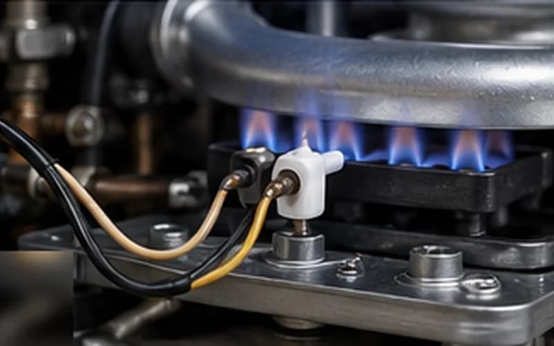
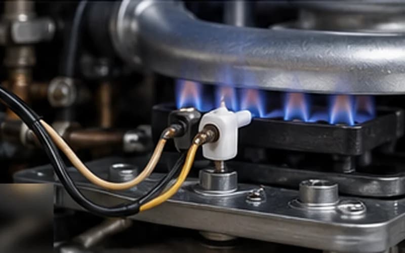
Ignition failure is the number one fault category on tankless water heaters — it accounts for approximately 35% of all service calls across every brand. The reason it is so common: the ignition chain involves more independent components than any other subsystem. The reason it is often misdiagnosed: technicians replace parts rather than test them. This guide provides a measurement-based approach that resolves most ignition failures without unnecessary parts replacement.
The Ignition Chain — Every Component That Can Fail
A successful ignition requires all of these to work simultaneously:
- checkWater flow above activation threshold (0.26–0.5 GPM depending on brand) — triggers the ignition sequence
- checkFlow sensor — must generate a pulse signal to the PCB
- checkPCB — must receive the flow signal, command the fan, confirm air pressure, then command ignition
- checkCombustion fan — must reach proving speed so the air pressure switch closes
- checkAir pressure switch — must close before gas valve opens
- checkGas supply — must be at adequate pressure at the unit inlet
- checkGas valve solenoid(s) — must open on command from the PCB
- checkIgniter electrode — must produce a high-voltage spark across a 3–4 mm gap in the burner
- checkBurner and orifice — must deliver the correct air/gas mixture for combustion
- checkFlame sensor / ionization rod — must detect and confirm the flame signal to the PCB
Any single failure in this chain produces an ignition failure code. The diagnostic challenge is identifying which link failed — without replacing the entire chain.
Systematic Diagnostic Sequence — Outer to Inner
Always work from external to internal, simple to complex, non-invasive to invasive. This sequence resolves 80% of ignition failures:
- checkStep 1 — Gas supply verification: open shutoff valve, test other appliances, measure static gas pressure (5–7" WC NG; 11" WC LP). Do this before opening the unit.
- checkStep 2 — Visual and auditory observation during ignition attempt: listen for fan (proves airflow), gas click (solenoid opening), spark (igniter firing). Missing sounds guide you to the failed component.
- checkStep 3 — Reset and attempt ignition with increased flow: open two hot-water fixtures to guarantee flow above the activation threshold. This eliminates flow-related ignition failure from the list.
- checkStep 4 — Inlet filter screen: remove and inspect for sediment or scale. A blocked screen restricts flow. Clean and reinstall.
- checkStep 5 — Flame sensor rod cleaning: 0000 steel wool on the rod tip. Resolves ~45% of all ignition failure cases.
- checkStep 6 — Vent inspection: both intake and exhaust terminations. Check for debris, ice, bird nests, and proper clearances.
- checkStep 7 — Igniter test: measure electrode resistance and gap. Confirm spark is occurring (listen for tick during ignition attempt).
- checkStep 8 — Gas valve test: measure solenoid coil resistance. Confirm PCB is sending drive voltage to the valve.
Listening-Based Diagnosis — What Sounds Tell You
During a live ignition attempt, the sequence of sounds identifies where the chain is breaking:
| Fan runs, NO spark sound, no ignition | PCB is not commanding igniter OR igniter electrode has failed — check PCB output voltage and electrode resistance |
| Fan runs, spark occurs, NO flame | Gas is not reaching the burner — check gas valve solenoid operation, inlet pressure, and gas orifice |
| Fan runs, spark, brief flame then out | Ignition succeeded but flame sensor rod lost the signal — clean or replace the ionization rod |
| NO fan sound at all | Power issue (check breaker, fuse), PCB fan command failure, or seized fan motor |
| Fan runs, NO gas click | Gas valve solenoid not receiving drive signal from PCB, or solenoid coil has failed (open circuit) |
Measuring Flame Sensor Ionization Current
If cleaning the flame sensor rod does not resolve the fault, test the ionization current directly. This measurement confirms whether the flame signal is reaching the PCB at sufficient strength.
- checkSet multimeter to DC microamps (µA). Most meters have a 200µA or 2000µA range.
- checkDisconnect the flame sensor lead from the PCB. Connect the multimeter in series: one probe to the wire lead, the other to the PCB terminal.
- checkAttempt ignition. Read the microamp value once the flame establishes.
- checkFunctional: 1.5–3.0 µA DC (varies by brand — check OEM spec). Below 1.0 µA is marginal. Above 5.0 µA may indicate a short to ground.
- checkIf current is below 1.0 µA even with a recently cleaned rod: rod needs replacement. If current is within spec but the PCB still shows ignition failure: PCB flame detection circuit may be faulty.
Igniter Electrode — When to Replace vs. Adjust
A spark gap that has widened beyond spec (due to electrode erosion) produces a weaker spark that may not reliably ignite the gas/air mixture, especially at lower gas pressures. A cracked ceramic insulator produces a spark that grounds out through the crack before reaching the gap.
| Standard spark gap (most brands) | 3.0–4.0 mm. Measure with a feeler gauge or spark gap tool. |
| Electrode erosion limit | Gap > 5 mm — replace the electrode; do not attempt to bend it to reduce the gap |
| Igniter continuity test | Resistance measured across the electrode: 10–30 kΩ (verify with model-specific spec) |
| Ceramic insulator inspection | No cracks, no carbon tracking (dark streak), no chipping at the tip |
When to Suspect the PCB or Gas Valve
PCB and gas valve failures are real, but they are also over-diagnosed. A technician who cannot find the cause of ignition failure after completing all the above steps should suspect these components — but only after confirming that all sensors, wiring, and mechanical components test within spec.
- checkGas valve test: disconnect the solenoid connector and measure coil resistance. Typical range: 25–60 Ω per coil. Verify the PCB is sending 12–24V DC to the valve terminal during an ignition attempt.
- checkPCB test: measure the PCB's output drive voltage at the igniter terminal during an ignition attempt. If the igniter is disconnected and there is no output voltage, the PCB igniter driver circuit has failed.
- checkWiring inspection: most 'PCB failures' are actually wiring failures — a corroded connector, a pinched wire under the unit cover, or a terminal that has backed out of its housing. Inspect every connector in the flame sensor, igniter, gas valve, and flow sensor circuits before condemning the PCB.
Gas valve replacement must be performed by a licensed gas fitter. The valve contains precisely calibrated orifices and pressure-regulating components that cannot be field-adjusted.
Video Guide
Tankless Water Heater Ignition Failure — Step-by-Step Troubleshooting Guide
Use HeatDiagnose for guided step-by-step repair
Enter your brand, model, and error code — and get a yes/no diagnostic flow built from OEM service procedures.
Frequently Asked Questions
How do I know if my flame sensor rod needs cleaning or full replacement?expand_more
Clean it first — oxidation is the most common cause and cleaning takes 2 minutes. After cleaning, if the unit still fails to ignite: test ionization current with a multimeter. If current is consistently below 1.0 µA DC with a clean rod, or if the ceramic insulator is cracked, replace the rod assembly.
Can humidity cause ignition failure on a tankless unit?expand_more
Yes, indirectly. High humidity accelerates oxidation on the flame sensor rod and causes moisture to form on igniter ceramic insulators, creating a conductive path that bleeds off the high-voltage spark before it reaches the gap. Units in basements or high-humidity environments should have their ignition components inspected annually.
Does ignition failure shorten the life of the gas valve?expand_more
Repeated ignition failures that cause the control board to attempt ignition multiple times per call do increase the number of solenoid actuations on the gas valve. Valve solenoids have a finite cycle life (typically 100,000+ cycles). Units that have had years of ignition problems may have accelerated solenoid wear. Address the root cause promptly.