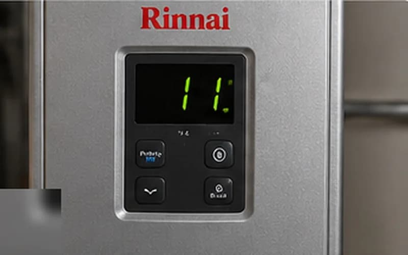
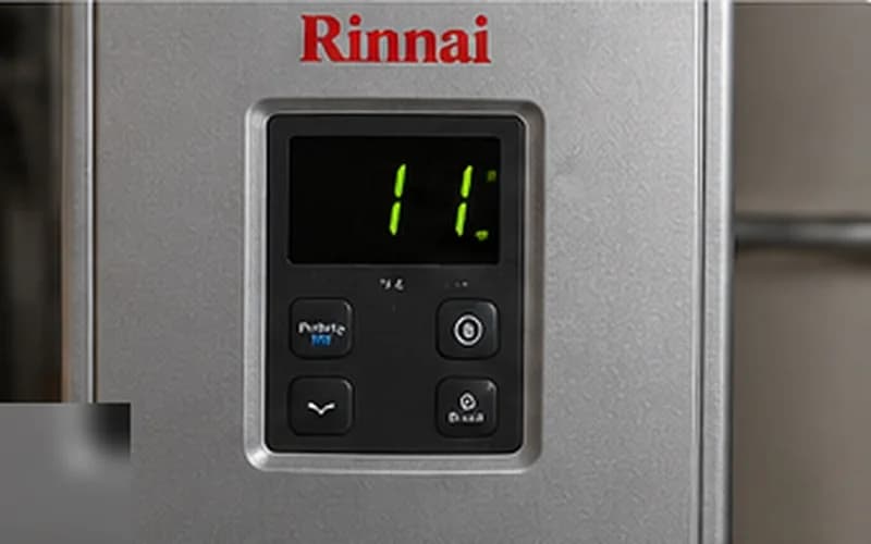
Rinnai error code 11 is triggered when the control PCB fires the igniter and opens the gas valve but the ionization rod does not detect a stable flame within the ignition time window. The unit makes up to three ignition attempts before locking out and displaying code 11. Understanding the ignition sequence — fan prove, gas valve open, spark, ionization detect — lets you identify exactly where in the chain the fault is occurring, rather than working through an unstructured checklist.
Rinnai Ignition Sequence — What Happens Before Every Hot Water Call
Knowing the sequence tells you what to listen for during a diagnostic attempt:
- check1. Flow sensor detects water flow above activation threshold (0.40 GPM standard; 0.26 GPM on Sensei models)
- check2. Control PCB commands the combustion fan to run — listen for the fan to ramp up to proving speed
- check3. Air-proving pressure switch closes, confirming adequate combustion airflow — if this switch does not close, ignition aborts (code 14 or 11 depending on model generation)
- check4. Gas valve solenoids open — a soft click, not always audible
- check5. Igniter sparks — an audible tick-tick-tick-tick for approximately 3 seconds
- check6. Ionization rod detects the flame and closes the safety circuit — sparking stops, burner runs
- check7. If ionization is not confirmed after 3 seconds: gas valve closes, sparking stops, one retry
- check8. After three failed attempts: hard lockout, code 11 displayed
During a service call, attempt ignition while listening carefully. If you hear the fan spin up, the gas click, and sparking, but ignition fails, the problem is in the burner itself (gas delivery or ionization). If you hear the fan but no sparking, the igniter is suspect. If there is no fan activity, check the pressure switch or PCB.
Gas Pressure Specification and Testing Method
The most direct way to rule out gas supply as the cause of code 11 is a manometer reading at the unit's gas inlet port. Do not rely on testing other appliances alone — a supply line can have adequate pressure for a furnace pilot but insufficient dynamic capacity for the Rinnai's burner demand.
| RL/RU/RUR — NG static pressure | 5.0–7.0" WC; minimum 3.5" WC |
| RL/RU/RUR — NG dynamic pressure | Must remain ≥ 3.5" WC at full firing rate |
| RL/RU/RUR — LP static pressure | 11.0" WC; minimum 8.0" WC |
| RL/RU/RUR — LP dynamic pressure | Must remain ≥ 8.0" WC at full firing rate |
| Gas inlet port location | 1/8" NPT port on gas valve body or inlet manifold — use a soapstone or brass plug to seal after testing |
Ionization Rod Inspection and Cleaning
The Rinnai ionization rod (also called the flame sensor rod) is located in the burner assembly. On most RL and RU models, removing the front cover gives direct access. The rod tip must be clean and bright metal. A gray or brown coating means oxidation is present and the rod must be cleaned.
- checkShut off gas at the service valve and cut power at the circuit breaker before accessing the burner.
- checkLocate the ionization rod — it has a ceramic insulator collar and connects to a single wire lead. It is shorter and has a different profile than the dual-wire igniter electrode.
- checkClean the rod tip with 320-grit emery cloth or 0000 steel wool. Wipe in one direction along the rod axis — approximately 10 strokes is sufficient. The metal should look bright after cleaning.
- checkInspect the ceramic insulator: a crack or carbon tracking (a thin dark line on the ceramic surface) means the insulation path to ground is compromised. Replace the rod.
- checkCheck the lead wire connection at the rod and at the PCB connector — corrosion at either end is a common cause of intermittent code 11.
Do not apply lubricant or anti-seize to the ionization rod. Any contamination on the rod tip will prevent ionization detection.
Igniter Electrode — Gap and Continuity
If cleaning the ionization rod does not resolve code 11, and you confirmed the gas supply is adequate, test the igniter electrode. This is the dual-wire component that produces the spark.
| Igniter electrode gap (RL/RU series) | 3–4 mm (0.12–0.16") |
| Igniter electrode gap (Sensei series) | 3.5–4.5 mm — check model-specific manual |
| Igniter resistance (functional) | 10–30 kΩ measured across electrode terminals |
| Failed igniter | ∞ resistance (open element) — replace electrode |
| PCB drive voltage at igniter | ~10–20 kV pulse. Do NOT measure with standard multimeter. |
Minimum Flow Rate and Water Inlet Check
Rinnai's minimum activation flow rates are among the lowest in the industry, but low-flow conditions still occur. A flow rate just at or below threshold causes the flow sensor switch to oscillate open/closed, creating a condition where the ignition sequence starts but the gas valve never fully opens.
| RL/RU/RUR activation flow rate | 0.40 GPM minimum |
| Sensei RSC160iP / RSC199iP | 0.26 GPM minimum (Rinnai's lowest) |
| V-series (V53, V65, V75) | 0.40 GPM minimum |
| Inlet filter screen location | Cold-water inlet fitting — unscrew and extract mesh screen |
If the unit only faults at a specific fixture (one shower but not others), check that fixture's aerator or showerhead flow rate. WaterSense-certified fixtures may restrict flow below Rinnai's activation threshold.
Vent System Inspection for Code 11
Unlike some brands, Rinnai uses an air-flow proving pressure switch in many models. If the combustion fan runs but the pressure switch does not close within the expected time, the PCB may abort ignition before the gas valve opens — displaying code 11 rather than a dedicated vent fault. This happens when the vent system has a restriction that prevents the fan from achieving proving pressure.
- checkInspect the exhaust and intake terminations for debris, ice, or bird nests.
- checkVerify vent pipe joints are all fully seated and secured. A partially unseated joint creates a leak that prevents proving pressure from building.
- checkOn Category III stainless vent, check that the vent sections are lapped in the direction of airflow (outer section upstream, inner section downstream on the exhaust side).
- checkOn PVC vent, verify all solvent-welded joints are fully cured and no cracks are present — PVC vent that has been thermal-cycled in outdoor sections is prone to cracking.
Video Guide
How To Fix Rinnai Tankless Water Heater Code 11 — Ignition Failure Troubleshooting
Use HeatDiagnose for guided step-by-step repair
Enter your brand, model, and error code — and get a yes/no diagnostic flow built from OEM service procedures.
Frequently Asked Questions
How do I reset Rinnai error code 11?expand_more
Press the On/Off button to power the unit down. Wait 30 seconds. Press On/Off again. The unit will attempt to restart on the next hot-water demand. If code 11 returns in the same cycle, proceed with the diagnostic sequence above.
Why does Rinnai code 11 only happen in winter?expand_more
Winter-specific code 11 almost always points to the venting system — specifically the exhaust termination partially iced over, the condensate drain frozen (on condensing models), or very cold gas supply pressure on LP systems where the propane tank is cold and LP vaporization pressure is reduced. Check outdoor terminations and, for LP, confirm the tank is not nearly empty (partial pressure).
Is there a difference in diagnosing code 11 on a Rinnai RL vs. Sensei?expand_more
Yes. Sensei (RSC series) has a lower minimum flow rate (0.26 GPM) and a more sensitive combustion system. It also has a more detailed service menu accessible via the control panel. The ionization and igniter components are similar, but the Sensei's PCB runs more pre-ignition checks before opening the gas valve, so pressure switch faults are more commonly the cause of code 11 on Sensei than on RL/RU series.